[4] Electric Defense 2
By Victor
Electric weapons 101
In a world ruled by electricity, taking advantage of its power can determine the fate of an individual, either by using it to run computers and sophisticated devices in order to gain advantage over your adversaries or simply using its raw power in an offensive way. Nowadays, when nearly every device and home appliance has its own electric circuit, it doesn’t take much skill to turn inoffensive circuits into dangerous electric weapons.
Electric weapons haven’t changed much since they were devised, the main principle of operation behind all of them is to create an electric potential high enough so current can flow inside the body, overflowing the nervous system with electric signals in an extremely painful way, losing control over the muscles, causing them to contract and leaving the subject incapable of fighting back even after the discharge has ceased due to the muscles needing some time to recover.
These electric weapons have many advantages, since they usually aren’t lethal, leave little to no evidence after having been used and just require a slight contact with the subject in order to do their job, a good tool to have to get out of a threatening situation without any further consequences.
Understanding how they work
One of the most important equations in electronics is voltage equals current times resistance (V = I × R). Now, for our electric weapon we need a lot of voltage; enough so electrons want to fly off the electrodes, enter the body of our attacker, and be sucked again into the circuit. If we increase the voltage we’ll decrease the output current: that means we’ll need a considerable amount of input current to start with, and 9 V alkaline batteries are not the best choice. Ni-Mh batteries are better, but they can’t come close to lithium batteries in terms of current delivery and energy density. We would need at least three of them in series to get a nice input voltage to start with. For practical reasons I’ll use a 9 V Ni-Mh battery, although lithium battery packs are advised.
Now we need to find a way to turn those 9 volts into 10000 volts at least, that will give us around 1 cm spark, enough to jump through clothes directly into the body, although our final voltage will probably be around 15000 volts. One of the best and simplest ways to increase a voltage is to use magnetism, this is, temporarily storing electric energy as magnetic energy, only to be converted
back again with a much higher potential, but lower current. We will rely on the basic laws of magnetism, which state that any change in magnetic field passing through a loop of wire will create an electric potential. This potential is directly related to the number of turns in the loop: the higher this number is, the higher the voltage will be.
To put these laws in practice we’ll use a flyback transformer. Flyback transformers consist of two coils, a primary and a secondary, wound around a ferrite core. This ferrite core stores the magnetic field created by the primary and when it collapses it gets transformed into a higher voltage by the secondary. According to the magnetism laws mentioned before, the ratio of turns of copper wire must be very high, around 1:100 or higher, in order to produce high voltages. A 555 timer will provide the electric pulses needed to alternate the magnetic field.
To further amplify the voltage a Cockcroft-Walton multiplier is used at the output of the transformer, this simple circuit relies on capacitors, which store electric charges and allow AC current to pass, and diodes, which act like check valves, only allowing the charges to travel forward, in combination the potential is increased while the current diminishes at each stage.
Getting started
After the concepts are clear we can start building our electric weapon or stun gun. We’ll start by gathering all our electronic components, an electronic “junk box” can help in some cases.
Parts needed
- Some broken CFL bulbs
- 555 timer chip
- 220-470 μF 25volt capacitor
- 10 μF 25 volt capacitor
- 1 μF 25 volt capacitor
- 5.6 nF capacitor (film or ceramic)
- Switch (flush preferred)
- Pushbutton
- Battery connector
- MOSFET of choice (IRF540)
- 10k Potentiometer
- 470R, 2x330R, 10R Resistors
- (20x) UF4007 or BA159 diodes (or any fast recovery diode) you can also use 10x 2-3 kV rated
- (10x) 1 nF 3 kV capacitors
- 2x Screws, nuts and locking washers
- Plastic box or case (non metallic)
Tools needed
- Soldering iron
- Drill
Construction
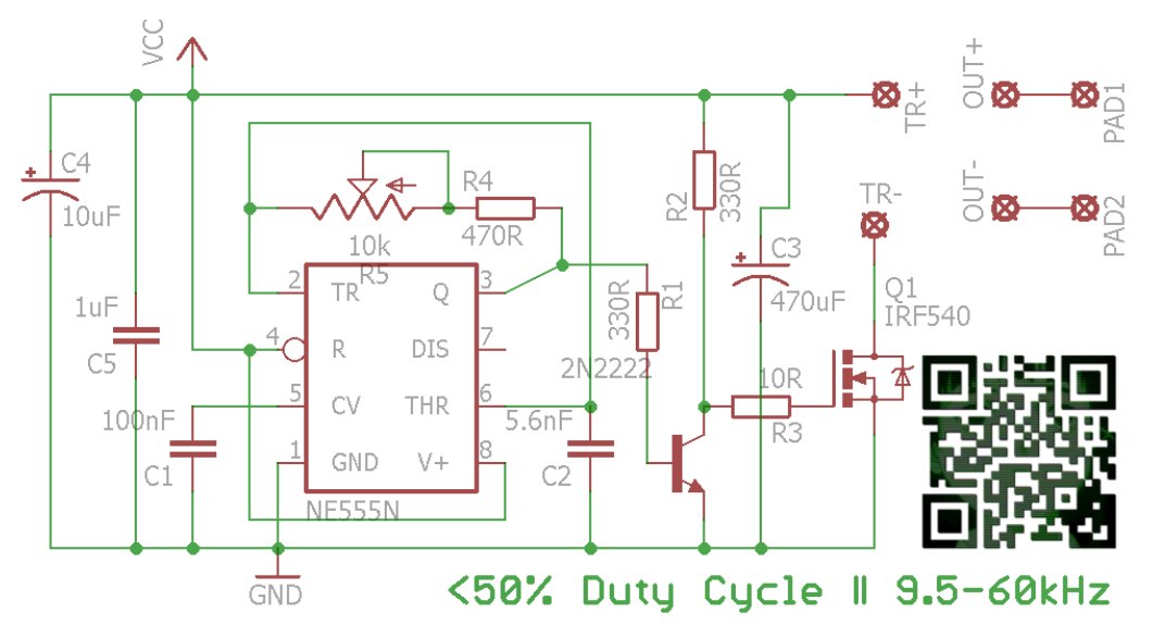
The flyback driver board is assembled first. Follow the circuit diagram to assemble it. To avoid voltage spikes caused by the discharges of the stun gun, make traces as short as possible. Wire bridges if any should be flush with the board and must be as short as possible. Use copper clad boards or prototype boards with appropriate trace width for high current sections. Build the multiplier on a different board. If you’re unsure about how to connect the multiplier to the transformer on the driver board you can connect a neon bulb to the output of the transformer and power the driver. The electrode with a brighter glow around will be the negative, and it will be connected to the negative of the multiplier. The dimmer one will be the positive.
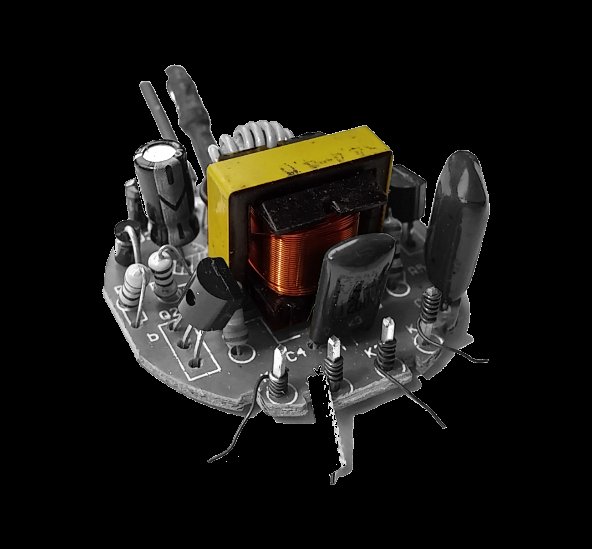
To make the flyback transformer, a transformer from a fairly big CFL PSU is desoldered. After removing the protective tape, the ferrite core is evenly heated up with a small torch until the glue holding it together melts. The two “E” parts of the core are extracted with the help of some pliers. Now that the windings are exposed, snip the wire and begin pulling it out until there’s nothing left but the plastic to hold a new winding. Clean glue residues with alcohol. Tightly wind around 20 turns of ~24 AWG enameled wire to create the primary. For the secondary I used a very thin enameled wire, around 35 AWG as calculated according to its resistance per meter. Wind as many turns as necessary to fill the transformer, probably around 1000 turns in this case. Solder the ends of each coil to a lead at the base of the transformer. To finish it all, dip the transformer in hot wax, waiting around half a minute so it can get between the windings. Some kind of cyanoacrylate glue could work too. Although this isn’t necessary it gives me more confidence; as in many occasions I could smell ozone being generated by the transformer, probably indicating a short.


To make the multiplier, a perforated board without pads can be used. Assemble the circuit keeping clearances in mind. When soldering and trimming the leads, avoid pointy ends as electrons like to jump off them. This effect is known as corona discharge. Leave at least 5 mm between the capacitor leads. Using a padded perfboard is not advised as the copper pads make it difficult to respect the clearances. In this case 1 nF capacitors rated 3 kV have been used in
conjunction with BA159 diodes. As it can be seen, 20 diodes have been used. This is because the output voltage of the transformer can get up to 2 kV. Instead of ordering 2 kV rated diodes, 2 diodes in series is capable of 1 kV reverse voltage. Each will work just fine.

CFL power supply with desired transformer.
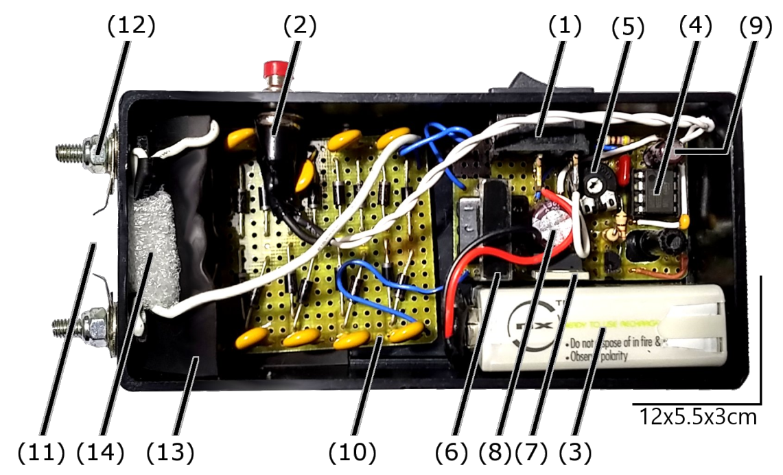
Laying the circuit inside the case is also important, try to maintain a distance between the high voltage multiplier and low voltage components. Holes for the switch and pushbutton are made in convenient locations. They are placed and soldered to the circuit. Use plenty of shrink tube and electrical tape in case of doubt. Double sided tape or hot glue can be used to hold the boards in place and packing foam to separate them. To make the output contacts, two holes are made through one extreme and two bolts are inserted with their nuts and locking washers, clamping the exposed output wires in between. Some sheet metal from a tin can is used to make the spark gap, which in this case is 1.3 cm apart. Experimenting with different configurations is encouraged, as arcing is kind of unpredictable. As an optional improvement, a capacitor can be connected between the output terminals. This will create beefier sparks that will pack a bigger punch. The capacitors should be rated for 15 to 20 kV, this can make them harder to find. Their capacitance value will vary depending on the space left in each case, as these capacitors tend to be quite big.
The trigger will be a pushbutton that will connect the battery to the 555 and flyback transformer. Avoid using pin 4 of the 555 as the trigger, as the voltage spikes will affect the performance of the circuit. As a measure of safety to avoid accidentally turning on the device, a switch is installed. Both the switch and the pushbutton should be rated for at least 3 amps.
To adjust the stun gun, open the case and hold it into the air, as leaving it on a desk or any other surface while performing this operation would include parasitic capacitances that will affect the correct adjustment. With the pushbutton constantly pressed, adjust the potentiometer with a screwdriver until the rate at which sparks occur is higher. Adjust the spark gap to be as wide as possible and repeat the operation until it can’t be further optimized.
Electric noise: a stun gun is probably one of the worst environments for a circuit to work. High current and high voltage pulses produced by the arc and the transformer induce voltage spikes inside the circuit. A couple of capacitors between power and ground to filter these spikes is fundamental but this doesn’t completely solves the issue. Insulating the 555 driver using a faraday cage made with conductive paint or HVAC foil tape could be a simple solution.
Other uses: The electric disturbances produced by this device can be strong enough to alter the normal operation of other electronic devices or even destroy them. Operating the stun gun at a distance closer than 2 cm from a circuit board will probably crash or brick it, although at this point one might just zap it if the intention is to destroy it. Adding a coil to the output of the stun gun with a small spark gap will amplify this effect, allowing you to mess with circuit boards locked behind a plastic casing. This won’t work with metal cases as they will absorb the energy produced by the magnetic field before it reaches the circuit.
Other ways of making a stun gun: One of the most used stun gun circuits uses a pulse trigger transformer. These transformers are hard to make and require isolating the coils with resin and purging the air to avoid shorts at the secondary. Both circuits are similar; the difference being the stun gun described here converts the voltage coming out of the first transformer using a Cockcroft-Walton multiplier, which is far easier to make from common components, while the standard one stores the output in a capacitor to discharge it though this second transformer, further amplifying it.
This same 555 driver circuit can be used without many modifications with bigger transformers, for example, to make electric fences.
Troubleshooting
- It just doesn’t work.
- Check if the battery is fresh, recheck connections, and make sure the 555 timer works.
- 555 and MOSFET are working but there’s no output.
- Check the transformer is connected. Check the output of the transformer with a neon bulb. If it doesn’t glow despite current flowing through the primary, it is shorted or there is a problem with it. Check the if transformer has been connected properly to the multiplier. Pay attention to the polarity.
- MOSFET/Transformer are overheating.
- Very low primary impedance. Increase turns at the primary or increase frequency. Check gate of the MOSFET, there should be a square wave there.
- It was working but now the output has dropped a lot.
- Check diodes on the multiplier with an ohmmeter in the megaohms range. Any diode with low or different reverse values than a new one is fried. Capacitors are not likely to fail, but they can be tested too. If diodes fry often, the output of the transformer is too high. Decrease the number of turns at the secondary or increase the rating of the diodes/put another diode in series. If you smell ozone/burning near the transformer it might be shorted. Test it in the dark to check for unwanted arcing or corona discharge.

(1) Switch
(2) Pushbutton
(3) Battery
(4) 555 driver
(5) Adjust potentiometer
(6) Flyback ransformer
(7) MOSFET or high power transistor
(8) Main capacitor
(8) Main capacitor (470 μF)
(9) Noise filter capacitors (10 and 1 μF)
(10) Multiplier board
(11) Spark gap
(12) Output terminals
(13) Rubber isolation
(14) Optional output capacitor